

Robustes Hochleistungs-Hochspannungs-Ladenetzteil
Holen Sie sich aktuelle Preis| Zahlungsart: | T/T |
| Incoterm: | FOB,CFR,CIF,EXW |
| Minimum der Bestellmenge: | 1 Piece/Pieces |
| Transport: | Ocean,Land,Air,Express |
| Hafen: | SHANGHAI,NANJING,QINGDAO |

| Zahlungsart: | T/T |
| Incoterm: | FOB,CFR,CIF,EXW |
| Minimum der Bestellmenge: | 1 Piece/Pieces |
| Transport: | Ocean,Land,Air,Express |
| Hafen: | SHANGHAI,NANJING,QINGDAO |
Modell: CCPS
Marke: IDEALTEKNIC
Herkunftsort: China
Ausgangsleistung: > 500W
Ausgabetyp: Single
Input Voltage: Three Phase 380vac
Input Frequency: 50/60hz
Working Principle: Pwm
Power Supply Type: Igbt-Based
Working Mode: Constant Voltage / Constant Current
Display Mode: Lcd
Control Mode: 10-Turn Potentiometers
Protections: Input Lack Phase, Ovp, Ocp, Otp, Short-Circuit Protections Etc., Ocp, Short Circuit And Load Dischargin
Applications: Capacitor Charging, Electrostatic Precipitator, Semiconductor Process, Lab Test / Hipot / Capacitor Charging
Cooling: Forced Air Cooling
Circuit Mode: Pwm
Output Voltage Range: 5 Kv ~ 60 Kv
Output Current Range: 100 Ma ~ 2400 Ma
| Verkaufseinheiten | : | Piece/Pieces |
| Pakettyp | : | Sperrholzkiste |
| Bildbeispiel | : |
|
| Herunterladen | : |
|

DC-Netzteil mit Hochspannungskondensator der CCPS-Serie
Überblick
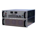
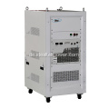
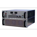
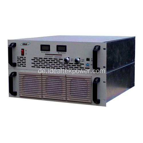
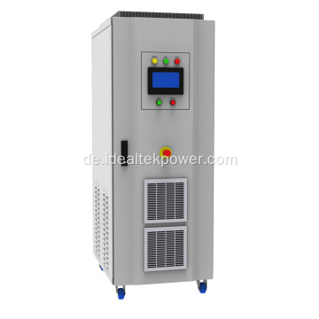
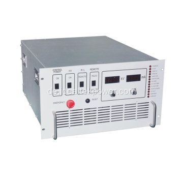
Das Hochspannungsnetzteil der Serie CCPS-6U ist eine verbesserte Version der Hochspannungs-Kondensatorladenetzteile CCP-6U. Es verwendet ein 19-Zoll-6U-Standard-Rack-Mount-Chassis mit einer Ausgangsleistung von bis zu 10KW und einem Ausgangsspannungspegel von 5KV / 10KV / 20KV / 30KV / 40KV / 50KV / 60KV, die die Hochspannungs-Ladenetzteile erreicht haben eine wesentliche Erhöhung der Ladekapazität der HV-Kondensator-Ladestromversorgungen im Rack auf der Grundlage der Aufrechterhaltung eines hohen Wirkungsgrads, einer hohen Ausgangsreaktionsgeschwindigkeit und eines schnelleren Schutzes und Beginns der Selbstwiederherstellung.
Die Frontplatte dieser Serie von Hochspannungsnetzteilen mit Kondensatorladung wird durch ein Potentiometer gesteuert, wobei die LCD-Anzeigen den Hochspannungsausgang anzeigen. Diese Serie von Kondensatorlade-HVPS kann mit einer RS485-Schnittstelle und einer Steuersoftware ausgestattet werden, um die Betriebsparameter des Kondensatorlade-HVPS zu steuern und zu überwachen.
Das Netzteil ist mit umfassenderen Schutzmaßnahmen ausgestattet, um einen langfristigen und zuverlässigen Betrieb des HV-Kondensatorladegeräts bei Volllast zu gewährleisten, wie z. B.: Eingangsphasenverlust, Ausgangsüberspannung, Überstrom, Überhitzung, Kurzschlussschutz usw auch mit einer Entladeschaltung ausgestattet sein, um Hochspannungs-Lade- und Entladebedingungen für einen wirksamen Schutz der Hochspannungs-Netzteile und der zu prüfenden Kondensatoren zu bewältigen.

Eigenschaften
l Kann als HV-DC-Netzteil oder als HV-Kondensator-Ladenetzteil verwendet werden.
l Ausgangsspannung einstellbar von 0 bis 100 %
l Ausgangsleistung: Durchschnittliches Laden @ 5KJ/S und die Spitzenladeleistung kann 12KW erreichen.
l Laden Sie im Konstantstrommodus und wechseln Sie in den Konstantstrommodus, bis er vollständig aufgeladen ist.
l Einzigartiges doppelt isoliertes System, starke Entstörungsfähigkeit.
l Zwangsluftkühlung, sehr robuste Ausführung.
Anwendungen
Kondensatoraufladung, Elektrofilter, Halbleiterprozess.
Sicherheitshinweise
1. Dieses Leistungsmodul hat einen HV-Ausgang, nur eine professionelle Person kann es bedienen.
2. Bitte stellen Sie vor dem Betrieb eine gute Erdung sicher.
3. Das Netzteil zum Aufladen des Kondensators hat eine geringe interne gespeicherte Energie, bitte KEINE Leerlauffunktion.
4. Halten Sie das Strommodul sauber und gut belüftet.
5. HV-Eingangs- und -Ausgangsanschlüsse oder HV-Last nichts berühren.
|
Input |
Connection mode |
Three-phase, four-wire (PE), TN-S supply mode |
|
|
Voltage |
380Vac±10% |
||
|
Frequency |
50Hz/ 60Hz ± 10% |
||
|
Current |
As per output power. |
||
|
Output |
Rated power |
6KW ~ 12KW (Max.) available ** |
|
|
Output voltage adjusting range |
5KV ~ 60KV available ** (For other output voltages, please contact us for details) |
||
|
Output current adjusting range |
0A ~ ****mA |
||
|
Output polarity |
Positive or Negative (both available) Client must choose one output polarity before ordering. |
||
|
Working mode |
Constant voltage (CV) / Constant current (CC) |
||
|
Accuracy (C.V.) |
Line regulation |
≤0.5% FS ± 1 digit (Output voltage change rate only caused by changes of input voltage over ± 10% range of variation) |
|
|
Load regulation |
≤1% FS ± 1 digit (Output voltage change rate only caused by full range load changes) |
||
|
Accuracy (C.C.) |
Line regulation |
≤0.5% FS ± 1 digit (Output voltage change rate only caused by changes of input voltage over ± 10% range of variation) |
|
|
Load regulation |
≤0.5% FS ± 1 digit (Output voltage change rate only caused by full range load changes) |
||
|
Temperature drift |
≤0.03% FS (Output voltage change rate every 8 hours after power on for half an hour) |
||
|
Ripple (p-p) |
≤0.5% FS (measured @ 80% ~ 100% rated output) |
||
|
Output cable |
HV connector and line provided by IdealTek. |
||
|
Efficiency |
≥90% |
||
|
Setting & Display |
Control mode |
Local |
10-turn potentiometer on front panel. |
|
Remote (Optional) |
RS485 communication interface. In line with MODBUS-RTU standard. The user can control and monitor the power supply via RS485 connection with computer, E.g: l Power ON / OFF l Output voltage & current setting & reading. l Working state monitoring (constant voltage, constant current, fault) |
||
|
Display mode |
41/2 LCD digital display |
||
|
Display error |
≤±0.5%FS ± 1digit (range: 5%~100% of the rated value) |
||
|
Display resolution |
As per output voltage & current values. |
||
|
Protection & Monitoring functions |
Input protection |
Input lack phase protection. |
|
|
Output over voltage protection (OVP) |
Power supply automatically cuts off output and alarms when output has over voltage. |
||
|
Output over current protection (OCP) |
Power supply automatically cuts off output and alarms when the output has over current. |
||
|
Over temperature protection (OTP) |
Power supply automatically cuts off output and alarms when the internal temperature of the power supply exceeds its threshold value. |
||
|
Output short-circuit protection |
Power supply automatically switches to CC working when the output has short-circuit. |
||
|
Over-loading capacity |
Withstand working with 1.05 times of rated current. |
||
|
Noise |
≤65dB |
||
|
Protection degree |
IP20 |
||
|
Cooling method |
l Forced air cooling l Forced air cooling + internal water-cooling loop. Direction: The lower part of the left and right sides - In and Top - Out wind. Differ as per output power rating. |
||
|
Inverter transient protection response time |
≤10us |
||
|
Working environment conditions |
Ambient temperature |
-5℃~+45℃ |
|
|
Humidity |
10%~80%(non-condensing) |
||
|
Height |
≤1000m |
||
|
Location |
Indoor use only No conductive dust, gas or steam that destroys the insulating medium No severe vibration and shock, good ventilation. |
||
|
Size (W*H*D) (mm) |
482*265.5*566.5 (19” 6U standard chassis) |
||
|
Weight |
Approx. 45Kg |
||
|
|
|||
|
Front panel description |
||||||||
 |
||||||||
|
No. |
Name |
Function |
Operation / display instruction |
|||||
|
F1 |
Control cabinet air inlet |
Control cabinet heat dissipation air inlet |
Keep it clean and smooth |
|||||
|
F2 |
Handle |
For moving and lifting purpose |
|
|||||
|
F3 |
Mounting hole |
For cabinet installing and fixing |
|
|||||
|
F4 |
POWER switch |
Supply electric ON/OFF switch |
Switch to ON position è Power ON Switch to OFF position è Power OFF |
|||||
|
F5 |
VOLTAGE |
Output voltage real-time display |
Digital LED display |
|||||
|
F6 |
CURRENT |
Output current real-time display |
Digital LED display |
|||||
|
F7 |
Indicator lights |
Real-time indication of module working state |
Indicator lights display |
|||||
|
F8 |
Voltage Adj. |
Output voltage adjusting |
Turn as icon, clockwise adjusting for increasing output voltage, anticlockwise adjusting for decreasing output voltage. |
|||||
|
F9 |
Current Adj. |
Output current adjusting |
Turn as icon, clockwise adjusting for increasing output current, anticlockwise adjusting for decreasing output current. |
|||||
|
F10 |
Analog port |
232/485 optional port (N/A for this unit) |
Please connect to DB9 port for communication with host. |
|||||
|
F11 |
Start/Stop (with lock) |
HV output start/stop |
Press down (green light ON) è HV START Press up (green light OFF) è HV STOP |
|||||
|
F12 |
Charging/Charged |
Charging / Charged state indicator light |
Charging lighted è Under charging. Charged lighted è Charging finished. |
|||||
|
Front Panel Indicator Lights Description |
||||||||
 |
||||||||
|
No. |
Name |
Function |
Operation / display instruction |
|||||
|
F13 |
Host indicator light |
Green LED light, lighted when power supply works as host unit under multi-unit parallel-working. Note: host indicator light lighted under single-unit working. |
Indicator lights display |
|||||
|
F14 |
Slave indicator light |
Green LED light, lighted when power supply works as slave unit under multi-unit parallel-working. Note: slave indicator light not lighted under single-unit working. |
Indicator lights display |
|||||
|
F15 |
C.V. indicator light |
Green LED light, lighted when power supply works under CV state. |
Indicator lights display |
|||||
|
F16 |
C.C. indicator light |
Green LED light, lighted when power supply works under CC state. |
Indicator lights display |
|||||
|
F17 |
Flashover indicator light |
Red LED light, lighted when power supply output has disruptive discharging. |
Indicator lights display |
|||||
|
F18 |
OC indicator light |
Red LED light, lighted when power supply has internal inverter output over current. |
Indicator lights display |
|||||
|
F19 |
Out short indicator light |
Red LED light, lighted when power supply has output short-circuits. |
Indicator lights display |
|||||
|
F20 |
OP indicator light |
Red LED light, lighted when output power of high voltage power supply exceeds the limit. |
Indicator lights display |
|||||
|
F21 |
Inhibit indicator light |
Red LED light, lighted when power output is prohibited by client's external nodes. |
Indicator lights display |
|||||
|
F22 |
OT indicator light |
Red LED light, lighted when power supply has internal module over temperature. |
Indicator lights display |
|||||
|
F23 |
Grid indicator light |
Red LED light, lighted when power supply has input abnormal (i.e.: lack phase or out of scope) |
Indicator lights display |
|||||
|
F24 |
IGBT indicator light |
Red LED light, lighted when power supply has internal inverter fault |
Indicator lights display |
|||||
|
F25 |
OV indicator light |
Red LED light, lighted when output voltage goes out of scope. |
Indicator lights display |
|||||
|
F26 |
Load OC indicator light |
Red LED light, lighted when output current goes out of scope. |
Indicator lights display |
|||||
|
F27 |
APS indicator light |
Red LED light, lighted when internal auxiliary power supply is working. |
Indicator lights display |
|||||
|
Back panel description |
||||||||
 |
||||||||
|
No. |
Name |
Function |
Operation / display instruction |
|||||
|
B1 |
GND |
Main circuit part, connected to earth. |
Separately connected to earth. |
|||||
|
B2 |
HV cabinet (Feedback) air socket |
For connection of HV cabinet and control cabinet. |
Connect to control cabinet (Feedback) air plug |
|||||
|
B3 |
Control cabinet (H-power) air socket |
For connection of control cabinet and HV cabinet. |
Connect to HV cabinet (H-power) air plug |
|||||
|
B4 |
Control cabinet input port |
Remote 485 signal input port |
Leave it unconnected if no 485 signal used. |
|||||
|
B5 |
Control cabinet DB9 port |
Remote control / reading port |
Connect in external analog signal for remote control / reading (i.e.: 0~10V) |
|||||
|
B6 |
Control cabinet DB15 port |
Remote start/stop, fault state TTL signal port |
Connect in external start/stop signal (i.e.: 24V) Connect in external analog signal for fault state indication (i.e.: TTL signal) |
|||||
|
B7 |
Control cabinet (Feedback) air socket |
For connection of control cabinet and HV cabinet |
Connect to HV cabinet (Feedback) air plug |
|||||
|
B8 |
Cooling fan (temperature-controlled) |
Exhaust fan, controlled by temperature inside the cabinet |
The higher the temperature inside cabinet, the faster the fan speed is. |
|||||
|
B9 |
IN 480V~600VDC |
Connects to DC480V~600V input |
Red is positive, black is negative. |
|||||
|
B10/11 |
HV-output |
Negative HV output connector |
Connection port |
|||||
|
B12 |
Power GND |
Positive output connector |
Connection port |
|||||
|
B13 |
HV cabinet (H-power) air socket |
For connection of HV cabinet and control cabinet. |
Connect to control cabinet (H-power) air plug |
|||||
|
Remote interface definition |
||||||||
|
|
||||||||
|
B4 Wiring diagram / B5 Internal wiring / B6 Wiring diagram |
||||||||
|
No. |
Name |
Function |
Operation / display instruction |
|||||
|
Z-1 |
485-A |
485-A |
485-A |
|||||
|
Z-2 |
485-B |
485-B |
485-B |
|||||
|
Z-3 |
Remote ON/OFF state node (optional) (N/A for this unit) |
ON/OFF state node + |
Power OFF, node closed Power ON, node open |
|||||
|
Z-4 |
|
ON/OFF state node - |
|
|||||
|
X1 |
Voltage remote control (optional) (N/A for this unit) |
Voltage remote control + |
0-10V signal for 0-15KV output voltage setting |
|||||
|
X2 |
|
Voltage remote control - |
|
|||||
|
X3 |
Current remote control (optional) (N/A for this unit) |
Current remote control + |
0-10V signal for 0-1000mA output current setting |
|||||
|
X4 |
||||||||
|
KV |
mA |
P (KW) |
Model |
KV |
mA |
P (KW) |
Model |
|
5 |
1200 |
6 |
CCPS-(N/P)6kW-5kV |
10 |
1200 |
12 |
CCPS-(N/P)12kW-10kV |
|
10 |
600 |
6 |
CCPS-(N/P)6kW-10kV |
15 |
800 |
12 |
CCPS-(N/P)12kW-15kV |
|
15 |
400 |
6 |
CCPS-(N/P)6kW-15kV |
20 |
600 |
12 |
CCPS-(N/P)12kW-20kV |
|
20 |
300 |
6 |
CCPS-(N/P)6kW-20kV |
30 |
200 |
6 |
CCPS-(N/P)6kW-30kV |
|
30 |
167 |
5 |
CCPS-(N/P)5kW-30kV |
40 |
150 |
6 |
CCPS-(N/P)6kW-40kV |
|
40 |
125 |
5 |
CCPS-(N/P)5kW-40kV |
45 |
133 |
6 |
CCPS-(N/P)6kW-45kV |
|
50 |
100 |
5 |
CCPS-(N/P)5kW-50kV |
50 |
120 |
6 |
CCPS-(N/P)6kW-50kV |
|
60 |
100 |
6 |
CCPS-(N/P)6kW-60kV |
60 |
200 |
12 |
CCPS-(N/P)12kW-80kV |
|
|
|||||||
l 0 ~ 10V Analogsignalsteuerung (DB -Grenzfläche) (+ac)
l RS -Kommunikationsschnittstelle (RS232 / RS485 Optional) (+RC)


Privacy statement: Your privacy is very important to Us. Our company promises not to disclose your personal information to any external company with out your explicit permission.
Fill in more information so that we can get in touch with you faster
Privacy statement: Your privacy is very important to Us. Our company promises not to disclose your personal information to any external company with out your explicit permission.